TABLE OF CONTENTS
WHY BOTHER WITH ROGERS AB1
Being really impressed with the sound of Chartwell LS3/5A and being aware of their limitations at the same time, I started looking for solution that would keep the magical midrange of LS3s but add a bit of weight to the bottom end. Similarly to many other people with the same problem, I came across Rogers AB1 subwoofer design – a dedicated subwoofer set for LS3/5A. Mixed opinions could be found on the internet. Some people like them a lot, whereas others, do not like them at all. I initially tried to obtain an original pair, but there are not many of them around for sale. However, there is a wealth of DIY materials on the Internet. Being an inquisitive person, I decided to give it a go and build a set myself. Enjoy! I did.
PLANNING
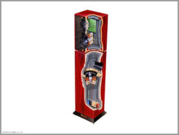
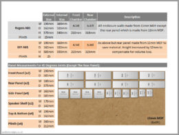
From what I found on the Internet, the original Rogers AB1 were made from 15mm MDF, with an exception of the back panel, which was made from 12mm MDF. Purely for economical reasons, I decided to make all panels from 15mm MDF. To compensate for the volume loss, my AB1s are 15mm taller than the original ones (see dimensions on the image below).
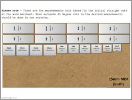
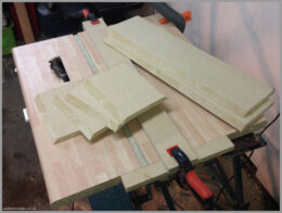
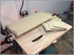
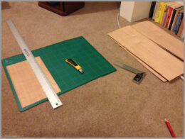
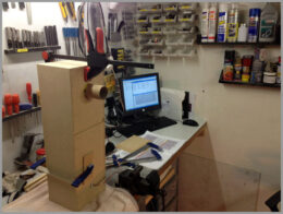
At the time I did not have a proper table saw and had to use a circular saw mounted up-side-down in a table top. The MDF was initially cut by the wood merchant to slightly oversized pieces. More precise 45 degree cuts were made in my workshop.
CROSSOVER & CONNECTORS
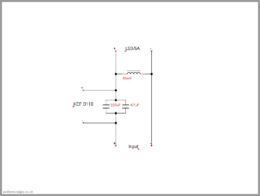
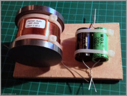
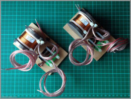
Rogers AB1 crossover design is fairly simple. It features 16mH iron core inductor and 220uF electrolytic cap in parallel with 4.7uF film capacitor. Design is based on the schematics from the ls35a.com website (provided by a gentleman called Andy Whittle, who, according to that website is the designer of the original Rogers AB1s). Precise specs of the components are listed in the table at the bottom of the page.
ENCLOSURE BUILDING
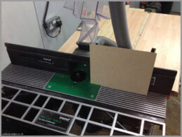
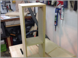
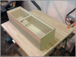
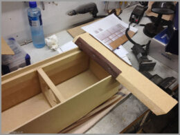
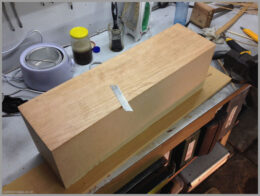
The Rogers AB1 DIY project was started from cutting the oversized wood pieces to the desired measurements and 45 degree angles. The homemade “table saw” turned out to be more precise than expected. Rear of the site, top and bottom panels where put on a router table where 10mm of MDF thickness was taken out. This was done to create a recess for the back panel (visible on one of the images below). Grooves in the side and front panels were routered, to create recess for the driver unit shelf (see images below).
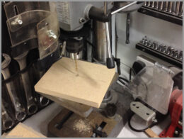
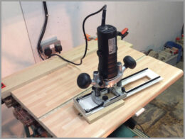
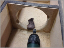
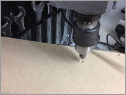
Centre of the driver unit shelf was predrilled, to allow for the router on the home made compass to be used. Driver holes were then cut out to accommodate the KEF B110 unit to be mounted from the top. Please note – because I decided to mount the unit in this particular way, it was necessary to chamfer the driver hole, to allow the driver to ‘breathe’. Unfortunately I forgotten to do it at the early stage, and had to do it after the enclosure was glued together (see images below). As you can imagine, this takes a lot longer, so it is much better to do it in advance. Luckily, I remembered to drill the driver unit mounting holes.
It was also necessary to create a small grove on the inside of front panel, just above the driver unit shelf to accommodate the basket of the KEF B110 unit.
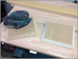
All the panels were put together to ensure that they fit properly. Panels were then glued using PVA wood glue, and once dry, sanded down starting with 80 and finishing on 120 Grit.
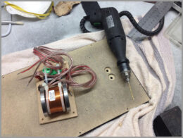
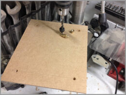
Spare rear panel was then used as a master template, to drill the rear panel mounting holes.
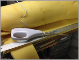
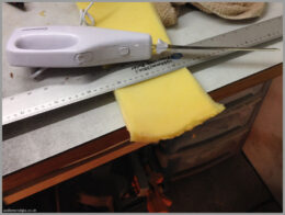
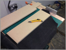
Upholstery foam was cut to correct sizes using electric kitchen knife. I experimented with different cutting methods and this by far gives the best results and flexibility. 2mm neoprene sheet was used to cut out one-piece rear panel seals. Seals were glued using contact adhesive. The rear panel screw holes were countersunk. Speaker terminal holes were enlarged to allow for slightly too short speaker terminals to be used. Rear panels were the spray painted back.
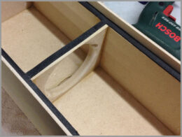
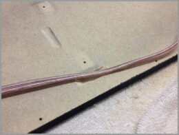
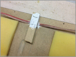
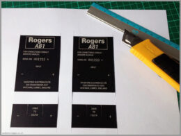
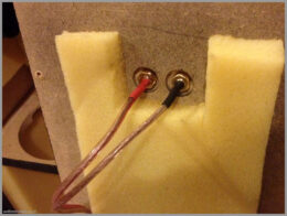
Two grooves were made on the inner side of real panels. One to accommodate basket of the KEF B110 unit and one to accommodate the wires going to the LS3/5A output terminals. Previously cut foam pieces were glued to the rear panel using spray contact adhesive. Crossovers where mounted just above input terminals. The wires going to the LS3/5A output terminals were placed in the grooves and sealed with silicone, to ensure that they are airtight. Rogers AB1 labels were mocked up in Photoshop and printed on good quality paper. Labels were then cut out, terminal holes were punched out using hole punch. Labels were sealed using clear car lacquer and glued to the back panels.
VENEERING
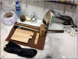
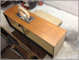
For this project I have decided to try traditional veneering method – hammer veneering. People have been using this method for thousands of years and there were plenty of video tutorials on YouTube, so it sounded like a good idea at the time. There are number of pros to this method, main ones being: reversibility, glue not affecting veneer finish and glue pulling veneer down while drying (no need for clamping). There are also some cons, like terrible smell of the glue, the fact that it can be dissolved in water and need of hot application. I did not want to spend a fortune while trying this method, hence, I have bought a wax heater from eBay instead of professional hot glue pot (£9.99 instead of £99) and I have also made my own veneer hammer from a piece of wood and a small sheet of 3mm brass (£5 instead of £30).
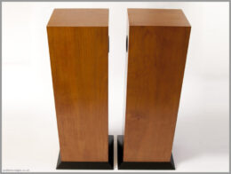
Having done all the preparations, work was started from cutting up the veneer into smaller pieces. Pieces were marked on the reverse to indicate which enclosure and side they should go onto. This was done to ensure continuity of the wood grain when the veneer is attached to the enclosure. Veneer sheets were then glued to the enclosures in the following order a – sides, b – tops, c – fronts. This order provided best visual result as the front sheet covers the edges of the side and top veneers. Once the glue dried, enclosures were sanded, starting with 120 and finishing on 180 Grit. Masking tape was applied on the veneer, and the bass reflex holes were cut out. Enclosures were then varnished using 4 layers of water based varnish. 240 Grit sandpaper was used to sand between coats of varnish.
The process resulted in fairly good looking enclosures, however, if you look closely at the finished enclosures, you can notice ‘stain’ patterns on the fronts – I was probably too enthusiastic with my hammer or the heat that I have applied. I find hammer veneering a lot more difficult than it looks on YouTube videos. I probably need more practice, nonetheless, I find the PVA glue and clamps a lot more user friendly than hammer veneering.
PORT TUNING & LISTENING TESTS
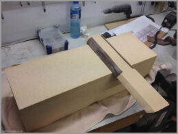
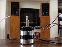
Initial port calibration was done during the building process (see image below) and it resulted in perfect vent tuning. Once these subwoofers were ready, they were measured again to ensure that they match initial measurements, and they did. The time has come to do first listening tests and much to my surprise, these DIY Rogers AB1 produced way to much bass. I tried different port lengths and different amounts of damping material inside the enclosures, with no success. Even with the foam plugs in the bass reflex ports, these Rogers AB1 subwoofers provided too much bass when coupled with my Chartwells LS3/5A. I also tried using drivers within the LS3/5A specification and the results were exactly the same. At this point my only conclusion was that AB1s are too sensitive in comparison to my 15ohm LS3s.
Number of listening tests were conducted with the L-Pad attenuator, with the aim of limiting sensitivity of the AB1s. Eventually the perfect setting was found – sensitivity was reduced by 7.5dB.
L-Pad attenuators were replaced with good quality, high power resistors.
I’d like to emphasise how important matching sensitivity actually is. Before installing permanent L-Pads the amount of bass was too overwhelming, and it made the whole set (Rogers AB1 + LS3/5A) sound disjointed. It was only since L-Pad installation when the subwoofers started properly blending with LS3s, making the whole set sound more coherent.
ENCLOSURE FINISHING
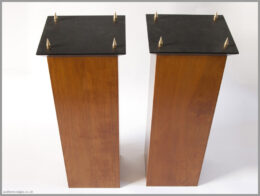
Finally, time has come to start putting things together. Previously cut foam sheets were glued into enclosures using spray contact adhesive. Drivers were mounted in the enclosures, all connectors were soldered and insulated using heat shrink tubing. The plinths were cut out of 25mm MDF and spray painted black. Spikes were attached at the bottom of the plinths and the plinths were attached to the bottom of the Rogers AB1 enclosures.
LIST OF COMPONENTS & PRICES
Table below shows list of the parts together with prices, necessary to build the set of Rogers AB1 described above. Please note – some of components that were already in my possession are not on this list (i.e. gasket, screws, PVA glue, etc.). The prices of the items listed below were correct at the time of writing this article.
| Total Time: | 35h |
| Total Cost: | £296.15 |
| Item | Details | Unit | Qty | Price Per Unit | Total Price |
| KEF B110 Driver | SP1003 | Piece | 2 | £60.00 | £120.00 |
| MDL Electrolytic Capacitor | 220uF, 100V, 10% | Piece | 2 | £4.22 | £8.44 |
| Jantzen Cross-Cap Capacitor | 4.7uF, 400V, 5% | Piece | 2 | £3.06 | £6.12 |
| Jantzen Ferrite Core Inductor | 16mH, 0,82Ω | Piece | 2 | £16.99 | £33.98 |
| OFC Wire | ø1.5mm | 1m | 3 | £1.00 | £3.00 |
| Speaker Binding Posts | Gold Plated | Pair | 4 | £3.00 | £12.00 |
| Brass Spikes & Nuts | M8, 11mm Long | Pack | 1 | £21.99 | £21.99 |
| Upholstery Foam | 25mm | Sheet | 1 | £14.95 | £14.95 |
| MDF | 2440x1220x15mm | Sheet | 1 | £18.00 | £18.00 |
| Bass Reflex Port | ø42mm/130mm | Piece | 2 | £3.98 | £7.96 |
| Cherry Veneer | 3150x210x0.6mm | Sheet | 2 | £13.60 | £27.20 |
| Ronseal Interior Varnish | Satin, 250ml | Can | 1 | £7.12 | £7.12 |
| £280.76 |
FINAL THOUGHTS
DIY of Rogers AB1 was a very enjoyable and rewarding project. Nonetheless, after countless listening tests I actually concluded that, although the AB1s give more body to LS3s, they also take away some of the magical midrange. The LS3s don’t have enough bottom end for me to enjoy them as my main speakers, so I was hoping that adding AB1s will fix this, and it did. However, it also took something away, something that I was not prepared to lose. I would be interested to try LS3/5As with the original Rogers AB1s, to see if my impressions would be the same (i.e. are the original AB1s tuned differently to the DIY version?).
Completed: March 2015 | Published: May 2015


